XPLORER Монитор переключения 59000-820
 | Монитор переключения, 59000-820 |
Operating Principles
The XPlorer Switch Monitor is designed to monitor the state of one or more single pole, volt free contacts connected on a single pair of cables and to report the status to XPlorer compatible analogue control equipment.
Electrical Considerations
The Switch Monitor is looppowered. The loop connections are polarity sensitive.
Protocol Bit Usage
The control equipment transmits a 10-bit message to the Switch Monitor:
The output (or forward command) bits from the control panel have the following function:
- Output bits 2 is not used.
- When Output bit 1 is set to logic 1 on two or more consecutive cycles, a self test is activated, resulting in a an analogue value of 64 being transmitted to the control panel.
When Output bit 0 is set to logic 1 on two or more consecutive cycles, the device simulates a fault condition resulting in an analogue value of 4 being transmitted to the control panel.
A response message is then sent by the Switch Monitor to the control equipment:
The interrupt bit is always set to logic ‘0’
The analogue value bits are set to return a preset value of 4 for open and short circuits, 16 during normal operation and 64 to signal an alarm.
The type bits are used to identify the type of unit responding. The type code of the Switch Monitor is set to 100 01 (Bits 2, 1, 0, 4, 3 respectively).
The Switch Monitor sends seven bits of data to confirm its address.
The alarm flag is set if another device is in alarm and has been polled for one second.
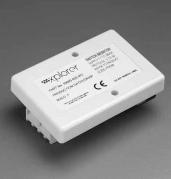
Mechanical Construction
The Switch Monitor is normally supplied with screws for surface mounting. It is designed for indoor use only.
The enclosure is moulded from the same white selfextinguishing polycarbonate as Apollo detectors
ТЕХНИЧЕСКИЕ ХАРАКТЕРИСТИКИ
| Address Range: | 64 to 126 |
| Operating Voltage: | 17–28V dc |
| Maximum current consumption at 24V:switch-on surge, max 100ms quiescent 20kΩ EOL fitted | 5mA |
| Operating temperature: | –20°C to +70°C |
| Humidity(no condensation): | 0–95% RH |
| Dimensions: | 65mm x 45mm x 22mm |
| Weight: | 31g |